Introduction
ZTerminal for Windows is the Windows program for setting up, checking and updating REDZ devices. It works with the LKM meter reader, the HUR IO modules, the HUR V-I metering module and the BKV wM-Bus module, and it is also a general terminal for serial and TCP links. This manual describes ZTerminal 5.0.0.
You open one connection, over a serial port or over TCP/IP, and then choose in the left bar what to do on it: work with a device on its own page, send and receive raw data on the Terminal page, or update firmware. The data that the terminal and the device pages send and receive, the connection events and the warnings are written to the session log at the bottom of the window. See the chapter The window.
1.1 Typical application
The Windows PC reaches LKM RTU, HUR IO, HUR V-I and BKV devices over a serial link: a COM port of the PC, for example a USB serial adapter. Over a TCP/IP network, a gateway or serial server reaches the Modbus devices (LKM RTU, HUR IO with its 8DO, 8DI, 8AI, 5AO modules, and HUR V-I); choose Modbus TCP or RTU over TCP for them in the Device pages list of the connection strip. See the chapters Requirements and start and The window.
1.2 The devices
- LKM: the meter reader that answers over Modbus RTU. On the LKM RTU page you read and write its settings and the IEC address of each meter, and read its monitoring values and the values it has read from the meters. See the chapter LKM.
- HUR IO: four Modbus input and output modules - 8DO (digital outputs), 8DI (digital inputs), 8AI (analog inputs) and 5AO (analog outputs). The HUR IO page shows the interface of the type you choose, and Detect type suggests which type is on the line. See the chapter HUR IO.
- HUR V-I: the metering module. The HUR V-I page shows the measured values with a phase diagram and the harmonics, and holds its configuration and its calibration. See the chapter HUR V-I.
- BKV: the wM-Bus module. The BKV page shows the module and its firmware, its radio configuration, its device list (which you can also open from and save to a DLF file) and the wM-Bus packets it receives. See the chapter BKV.
The Overview page reads the identity and the diagnostics of the selected product in one round. The Firmware page updates the firmware of LKM and HUR devices; it checks that the file is for the selected device before it sends anything. See the chapters Overview and Firmware update.
1.3 The terminal
The Terminal page sends text or hex data over the open link, once or periodically, typed in a box or read from a file, and shows what comes back. Over TCP/IP it can open several sockets to the same endpoint and send to all of them. See the chapter Terminal.
Requirements and start
2.1 Windows and the PC
ZTerminal for Windows runs on 64-bit (x64) Windows. It does not need a separate installation of .NET or of any other runtime: everything it needs is inside its program file.
To work with a device you need a way to reach it: a serial port of the PC (a COM port, for example a USB serial adapter) or a network connection to a TCP/IP endpoint.
2.2 One program file, no installation
ZTerminal comes as ZTerminal-5.0.0-win-x64.zip. The archive holds a single file, ZTerminal.exe. Unpack it to any folder and start it from there; nothing is installed and nothing is added to the Start menu.
ZTerminal remembers your choices in a small settings file in your Windows user profile, in a folder named ZTerminal. It keeps the connection strip; on the Terminal page, the two send boxes with their mode and line end, the single or periodic mode and its period, the chosen file, the frame setting and what Received shows; the recent sends of each box; and the filter of the Log page. A change is saved about one second after you make it; a change that is still waiting is saved when you close the program.
Some things are not remembered on purpose: the RTS and DTR control lines, a running capture, the find boxes, the page and tab you had open, the mode, line end, sheet and column of the Send from file tab, the unit ids of the device pages, and the window position.
NOTE:
When ZTerminal starts, the session log shows where the settings file is. If a saved value cannot be used - for example a COM port that is no longer there - the program keeps its default for that value and writes a warning to the session log. If the settings file cannot be read at all, the program starts with its defaults and saves no settings during that run; the session log says so.
2.3 Starting ZTerminal
Double-click ZTerminal.exe. The window opens in the middle of the screen. If the screen is too small for it, ZTerminal makes the window smaller so that it fits.
ZTerminal starts on the Terminal page with no connection open; the connection strip says "Not connected". The pages in the left bar that need a connection stay unavailable until you connect. See the chapter The window.
The top of the left bar shows the version of ZTerminal and the date and time its program file was built. Near the top of the session log, a line gives the same version and says that the program has started. Give this version when you contact support.
The window
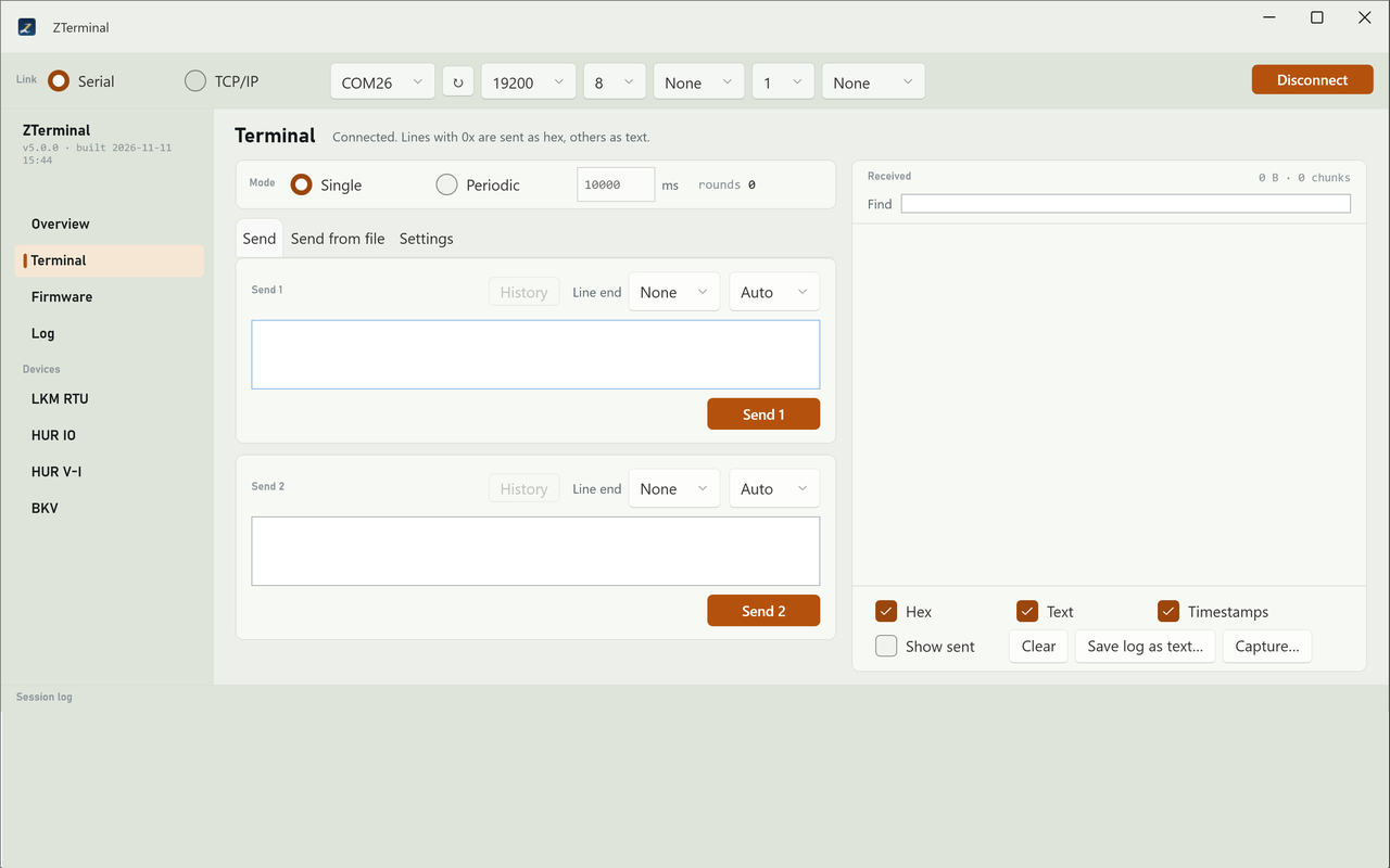
The window has three parts under its title bar: the connection strip at the top, the left bar with the page you chose next to it, and the session log at the bottom.
3.1 The left bar and its pages
The left bar lists the pages of ZTerminal. Click a page to open it. The table shows each page, the heading it is listed under and whether it needs an open connection.
| Page | Heading in the left bar | Needs an open connection |
|---|---|---|
| Overview | - | Yes |
| Terminal | - | No |
| Firmware | - | No |
| Log | - | No |
| LKM RTU | Devices | Yes |
| HUR IO | Devices | Yes |
| HUR V-I | Devices | Yes |
| BKV | Devices | Yes |
A page that needs a connection is unavailable while no connection is open, and becomes unavailable again when the connection closes. Terminal, Firmware and Log can always be opened.
Above the pages, the left bar shows the version of ZTerminal and when its program file was built.
When you open the LKM RTU, HUR IO, HUR V-I or BKV page with a connection open, the page reads the tab you see once from the device if that tab is still empty. This only reads; nothing is written to a device unless you press a button that writes. Which tabs do not read by themselves is described in the chapter of each device.
NOTE:
Only one page listens to the line at a time. The Terminal page shows incoming data only while it is open, and the BKV page listens for packets only while it is open. Data that arrives while another page is open is not shown at that time; data that no page has read can appear when you come back to the Terminal page, with the time at which it was read, not the time it arrived.
WARNING:
A periodic send started on the Terminal page is not stopped when you open another page. Press Stop on the Terminal page before you work with a device on its own page.
3.2 The connection strip
Under Link, choose Serial or TCP/IP. The strip then shows only the fields of that kind of link.
For a serial link, choose the COM port, the baud rate (300 to 115200 baud), the data bits (5 to 8), the parity, the stop bits (1, 1.5 or 2) and the flow control. The defaults are 19200 baud, 8 data bits, no parity, 1 stop bit and no flow control. If you plug in a USB serial adapter while ZTerminal is open, press the refresh button next to the port list (Refresh COM ports) so that the new port is listed.
NOTE:
Some serial drivers refuse 1.5 stop bits or 5 or 6 data bits. If the driver refuses the framing you chose, the error after Connect says so.
For a TCP/IP link, enter the host name or IP address and the TCP port (502 by default). The field after the port sets how many sockets ZTerminal opens to the same endpoint, from 1 to 32. If an endpoint does not accept the connection within 5 seconds, the connection fails with a message that names it.
- The delay field sets how long ZTerminal waits between the sockets when it sends (200 ms by default).
- Differentiate sends different data to each socket: a byte with the socket number, counted from 0, is added to hex lines, and a dash and the socket number to text lines. It is available only with more than one socket.
- Force Reconnect keeps trying every 2 seconds when the endpoint cannot be reached, and connects again when the other side closes the connection. Cancel or Disconnect stops it. A closed connection is noticed while the Terminal page is open.
- TCP keepalive checks an idle connection (after 10 seconds, then every second), so that an endpoint that disappears without closing the connection is noticed in about 20 seconds while the Terminal page is open. It takes effect when you connect.
Press Connect at the right of the strip. While the connection opens, the button reads Cancel and the strip is locked; the text next to the button shows the progress. When the connection is open, the text names the port or the endpoint and says it is connected, and the button reads Disconnect. If the connection cannot be opened, the text says why, and so does the session log.
While the Terminal page is open, if the other side closes the connection or reading fails, ZTerminal closes the connection and the text says "Link lost" with the reason. Over TCP/IP with Force Reconnect on, it then connects again by itself.
On a serial link, line errors that the port driver reports - parity, framing, overrun and buffer errors - are written to the session log as warnings, with a count when the same error repeats.
3.3 Modbus RTU or Modbus TCP
The Overview, LKM RTU, HUR IO and HUR V-I pages talk Modbus. On a serial link they always use Modbus RTU; there is nothing to choose.
When you choose TCP/IP, the strip shows Device pages with two choices. Modbus TCP (the default) sends Modbus TCP frames. RTU over TCP sends Modbus RTU frames through the TCP connection, for a serial server that passes the bytes on to a serial line unchanged. ZTerminal remembers the choice with the other strip settings. You can change it while connected; the device pages use the new choice from their next read or write.
The Terminal page does not use this choice: over a serial link and over TCP/IP it sends exactly what you type.
3.4 The session log at the bottom
The Session log panel at the bottom of the window is visible on every page. It shows the newest lines of the session log - what was sent and received, connections opened and closed, warnings and errors - always unfiltered. The filter of the Log page does not change it.
Select lines with Shift or Ctrl (Ctrl+A selects all) and press Ctrl+C to copy them, or right-click for Copy and Copy all. While the list is scrolled to its end it follows the newest line; if you scroll up, it stays where you are. The full log, with a filter, a find box and saving, is on the Log page. See the chapter Log.
Terminal
The Terminal page sends data over the open connection and shows what comes back. On the left are the Mode line and three tabs: Send, Send from file and Settings. On the right, Received shows the incoming data. The send buttons work only while a connection is open; the line next to the page title says "Connect to send and receive." until you connect.
The Device pages choice in the connection strip does not apply here: the Terminal page builds no Modbus frames and sends the lines as you set them on this page, over a serial link and over TCP/IP alike.
NOTE:
Received is filled only while the Terminal page is open. Data that no other page has read can appear when you come back, with the time at which it was read. See the chapter The window.
WARNING:
Stop a periodic send before you open another page: leaving the Terminal page does not stop it.
4.1 Sending once or periodically
Under Mode, choose Single to send once or Periodic to repeat. With Periodic, enter the period in milliseconds, at least 50 (10000 by default). One round sends the lines of the box one after the other; ZTerminal then waits the period and starts the next round.
Between two lines of a round ZTerminal waits 50 ms. With several TCP sockets, each line goes to every socket in turn, with the delay set in the connection strip between the sockets.
While a send is running, the send buttons read Stop and the text boxes are locked. Press Stop to end the send. A change to the mode or the period while a send is running applies to the next send. When the send ends, Mode shows the number of completed rounds next to rounds, and the line next to the page title says how many rounds were sent. A round that you stop half way is not counted.
4.2 The Send tab
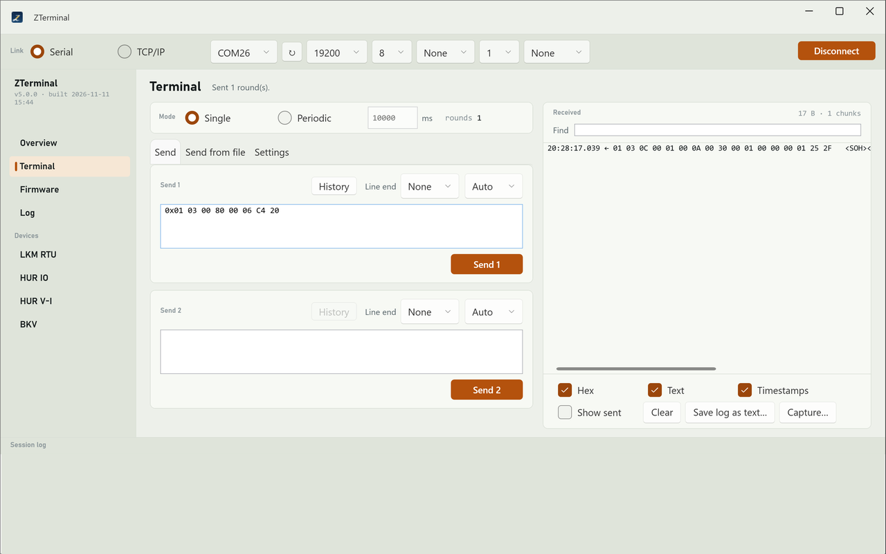
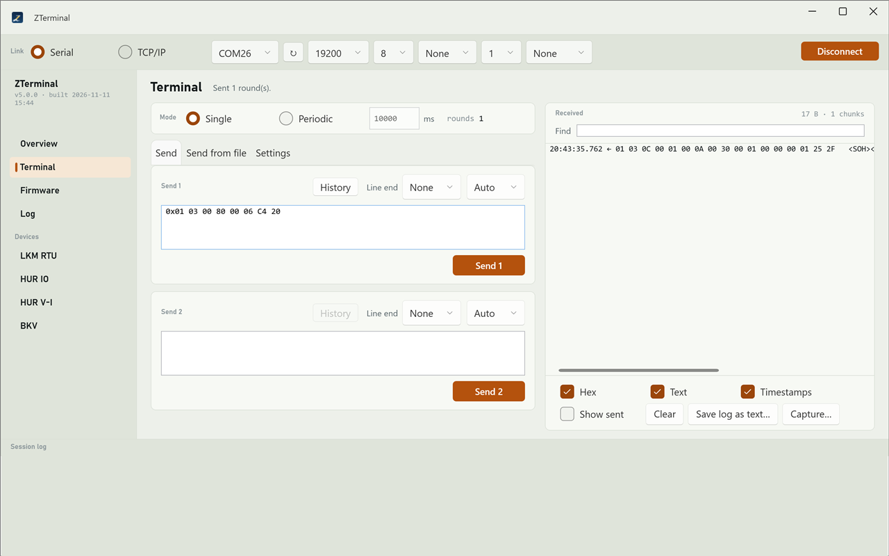
The tab has two boxes, Send 1 and Send 2, each with its own button. A button sends only its own box. Each line of the box is one frame; empty lines are skipped.
The list next to the box tells ZTerminal how to read the lines. With Auto, a line that contains 0x is sent as hex and any other line as text; Hex and Text force one way for every line. In a hex line, 0x prefixes, spaces, commas, dashes and colons are ignored, and the digits must come in pairs. In a text line, <CR>, <LF>, <TAB>, <STX>, <ETX>, <ACK>, <NAK> and <hh> (two hex digits) send that single byte.
Line end adds CR, LF or CRLF to the end of each text line; it is None by default. Hex lines get no line end.
Before anything is sent, ZTerminal reads every line of the box. If one line cannot be read - for example a hex line with an odd number of digits - nothing is sent: a red line above the tabs says what is wrong, and the session log gets the same warning.
History lists the recent sends of that box, newest first, up to 20. Choosing one puts it back in the box; it is not sent until you press the button. Only sends that started are listed, and the list is kept when you close ZTerminal.
4.3 Sending from a file
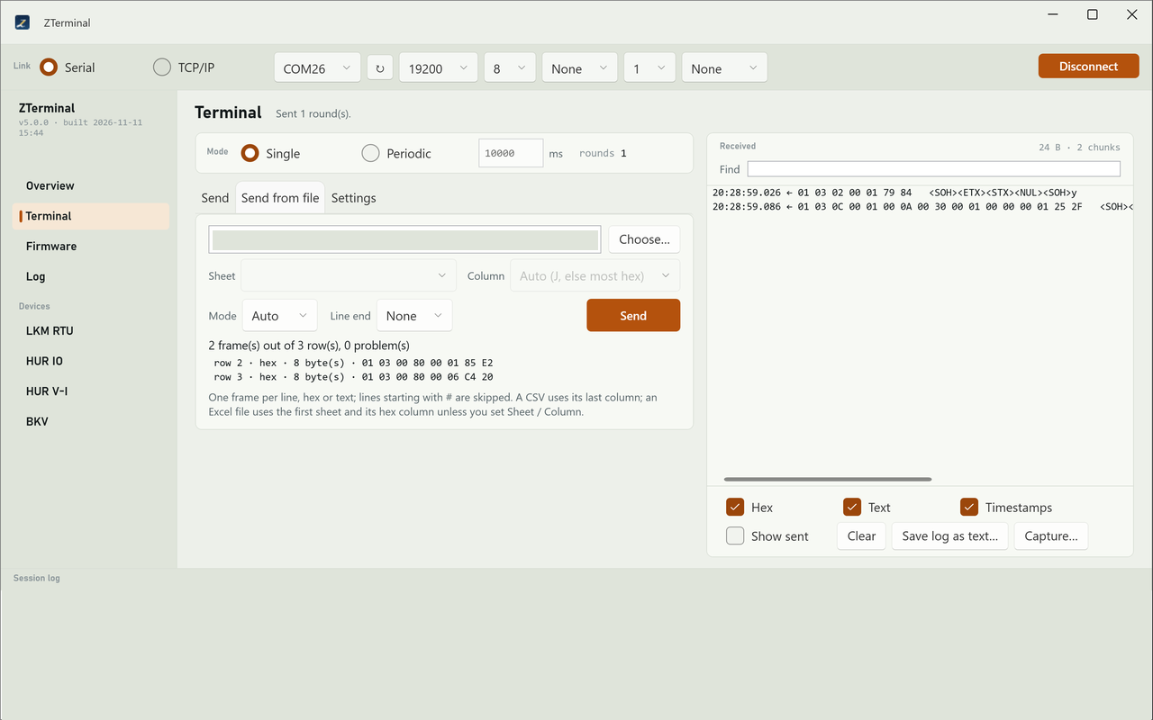
On the Send from file tab, press the Choose button and pick a text file (.txt), a CSV file (.csv) or an Excel file (.xls, .xlsx or .xlsm). A text or CSV file holds one frame per line, hex or text; lines that start with # are skipped, and a line that contains commas is read from its last column, that is, from the text after the last comma. In an Excel file every frame is a hex cell.
For an Excel file, Sheet and Column choose where the frames are. By default ZTerminal uses the first sheet and the column Auto (J, else most hex): column J, or else the column with the most hex cells. When you choose another file, both go back to their defaults.
Shortly after you choose the file, ZTerminal reads it and shows a summary - how many frames it found, where, and how many header rows and problems there are - and a preview with one line per row: the row number, whether the row is hex or text, and its length.
- In a text or CSV file, the first line is skipped as a header when it contains commas and the text after the last comma is not hex. A line that contains 0x but is not valid hex is marked "not hex" in the preview.
- In an Excel file, the cells above the first hex cell are skipped as header rows, unless they are numbers. After that, a cell that is not hex is listed as a problem and the summary turns red. If Excel has turned a hex cell into a number, the preview says so: format that column as Text in Excel.
If a line or cell cannot be read, nothing is sent and the red line above the tabs names the problem. Correct the file first.
The tab has its own Send button and its own Mode and Line end; in Auto, a cell that the file reading found to be hex is sent as hex even without 0x. Pressing Send reads the file again, so the preview always shows what is sent. Single and Periodic apply as for the boxes. Frames sent from a file are not added to the History of the boxes.
4.4 The Settings tab
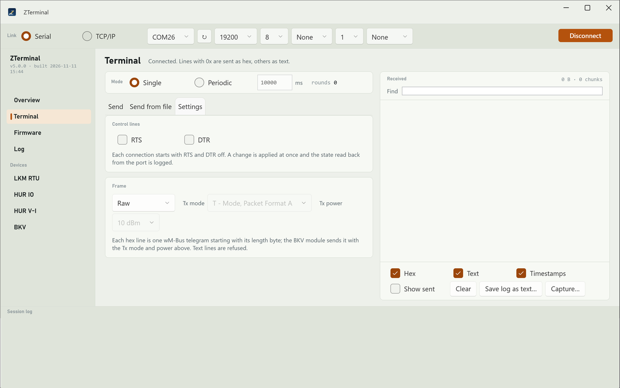
Under Control lines, RTS and DTR switch the two control lines of a serial port. Every connection starts with both off. A change takes effect at once, and the session log shows the state read back from the port. They are not available over TCP/IP; RTS is also not available when the flow control of the connection drives it.
Frame sets how lines go out. With Raw (the default) the frame adds nothing to a line. With BKV wM-Bus Tx, each hex line is one wM-Bus telegram that a BKV module on the line sends with the Tx mode and Tx power you choose: write the telegram starting with its length byte, and choose the mode (S, T or C mode; T mode by default) and the power (-1 to 13 dBm; 10 dBm by default). Text lines are refused in this frame.
WARNING:
ZTerminal remembers the Frame setting after a restart. Set it back to Raw before you use the terminal with a device other than a BKV module.
4.5 Showing the received data
Each piece of data that arrives becomes one line in Received: the time it was read, an arrow, the socket number in brackets (counted from 0) when several sockets are open, then the bytes in hex and as text. In the text, control bytes appear as <CR>, <LF> or <hh>. Above the list, ZTerminal counts the bytes and pieces received. The list keeps the newest 3000 lines.
Hex, Text and Timestamps choose what each line shows; changing them redraws the lines already in the list. Hex and Text cannot both be off: clearing the last one turns the other on.
Show sent adds what ZTerminal sends to the list, marked with an arrow pointing right. It applies to what is sent after you tick it; the byte counter still counts only received data.
Find jumps to the lines that contain your text, without hiding the others; case does not matter. Press Enter for the next match and Shift+Enter for the previous one; a counter next to the box shows where you are. Copy lines with Ctrl+C or with Copy and Copy all on the right-click menu. Clear empties the list and sets the counters to zero.
4.6 Saving the received data
To keep the received data in a file, press the Capture button and choose a file. From then on, every line that appears in Received is written to the file at once, with the time, the hex and the text, whatever the Hex, Text and Timestamps boxes show. An existing file is not overwritten: new lines are added to its end. Sent data goes into the file only while Show sent is on. A line under the counters shows the file and how many lines were written. Press Stop capture to end. If the file cannot be written, the capture stops and says why.
The Save log as text button saves the whole session log to a text file - the same content as the Save button on the Log page writes, not only the lines in Received. See the chapter Log.
Overview
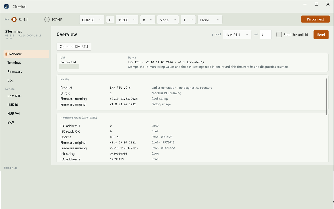
The Overview page answers one question: which product is on the line and in what state is it. You choose the product, press Read, and ZTerminal reads the product's identity and its diagnostics in one round. The page needs an open connection; while no connection is open, it cannot be chosen in the left bar.
5.1 Choosing the product and reading
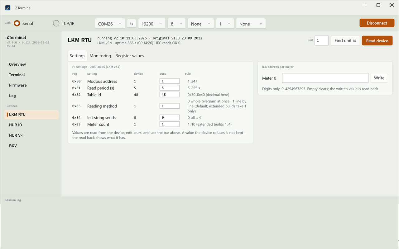
Choose the product in the product list: LKM RTU, HUR IO, HUR V-I or BKV. Only one product talks on the line at a time, so the page reads the product you choose and nothing else.
For the Modbus products (LKM RTU, HUR IO and HUR V-I) the page also shows the unit box with the unit id to read (1 when ZTerminal starts). Whether ZTerminal talks Modbus RTU or Modbus TCP follows the connection: always Modbus RTU on a serial link, and over TCP/IP the Device pages choice in the connection strip (see the chapter The window). For BKV the unit controls are hidden.
If you do not know the unit id, tick Find the unit id. Read then first asks the device for its own unit id and reads with the id it gives; the unit box is locked while the box is ticked. When the device answers, a line under the title shows the id it found and the unit box takes that id. Only one device may be on the line when you use this.
Read is available while the connection is open and no read is running. A thin progress bar runs under the title during the read.
The page only reads. It does not change any setting of the product.
5.2 What the page shows
The first card has two halves. Under Link you see connected or not connected and the name of the open port or socket; when more than one TCP socket is open, the number of extra sockets is added. With no connection the card says "Open a serial port or a TCP socket on the top bar first."
Under Device you see a one-line summary of the product after a read and, under it, a sentence about what was read. For an LKM the summary shows the running firmware. For a HUR module it shows the unit id and the original firmware, for a BKV the radio module type and the firmware version. Before the first read it says Not read yet.
Below that, the result is shown as cards. Each card has a title and rows; each row shows a name, the value read from the product and a short note on where the value comes from.
When you choose another product, the cards are cleared and the summary returns to Not read yet.
5.3 LKM RTU
The Identity card shows LKM RTU v2.x, the unit id, Firmware running and Firmware original. A second card lists the 15 monitoring values, and a third card the six settings.
The uptime counts from the last restart, and the LKM restarts itself once a day. The chapter LKM explains the values in detail.
5.4 HUR IO and HUR V-I
The Identity card shows the product you chose, the unit id the module reports, Firmware original, Firmware upgraded (or not upgraded when the module was never upgraded), Save on reset, Output on repower and Is reset. A counters card shows Reads and Uptime, the uptime as hours, minutes and seconds and in seconds.
For HUR V-I a third card, System and metering status, shows the module's four status values. The chapter HUR V-I explains them.
NOTE:
A HUR IO module does not report which of the four types (8DO, 8DI, 8AI or 5AO) it is. The Overview therefore shows the product name you chose. To find the type, use Detect type on the HUR IO page; see the chapter HUR IO.
5.5 BKV
The Identity card shows BKV wM-Bus collector, the radio Module type and the Device number. The Firmware card shows the Version, the Build date and the Name of the module firmware. The Radio and clock card shows the Device time, the Link mode, the LED flash time in milliseconds and whether the Address filter is on or off. A value the module did not return is shown as a question mark.
5.6 When the read fails
If the product does not answer, a red line under the title names the product and says what to check. For LKM RTU, HUR IO and HUR V-I it asks you to check the unit id, the framing (over TCP/IP, the Device pages choice in the connection strip) and which product is really on the line. When no answer came within the time limit, as with a BKV that does not answer, it asks you to check the connection and which product is on it. If Find the unit id was ticked and no device told its id, the line asks you to check the connection and that only one device is on the line. The same message is written to the log.
When nothing could be read, the cards from the previous read stay on the page; they are not from now. See the chapter Troubleshooting.
5.7 Opening the product's own page
After a successful read, a button appears under the title: "Open in" followed by the product, for example Open in LKM RTU. It takes you to that product's own page, where all its settings and values are.
For LKM RTU, HUR IO and HUR V-I, ZTerminal puts the unit id of the read into the unit box of that page and the page then reads the device with that id. The values on that page come from this new read, not from the Overview.
For BKV, the BKV page opens and reads by itself when its open tab is Device list, Module or Radio config and nothing has been read there yet.
NOTE:
The unit id is carried over, and the product's page talks to the device the same way as the Overview, because both follow the connection strip.
LKM
The LKM RTU page configures and checks an LKM optical meter reader over Modbus. It reads and writes the settings and the IEC address of each meter, and shows the LKM's monitoring values and the values it has read from the meters. Everything the page shows was read from the device; after a write, ZTerminal reads the device again and shows what it now holds.
After Read device, the page shows three tabs: Settings, Monitoring and Register values.
6.1 Reading the device
In the header, enter the unit id in the unit box (1 when ZTerminal starts). On a serial link the page uses Modbus RTU; over TCP/IP it follows the Device pages choice in the connection strip (see the chapter The window).
Find unit id asks the device for its own unit id. Only one device may be on the line. When it answers, a line under the header shows the id it found and the unit box takes that id.
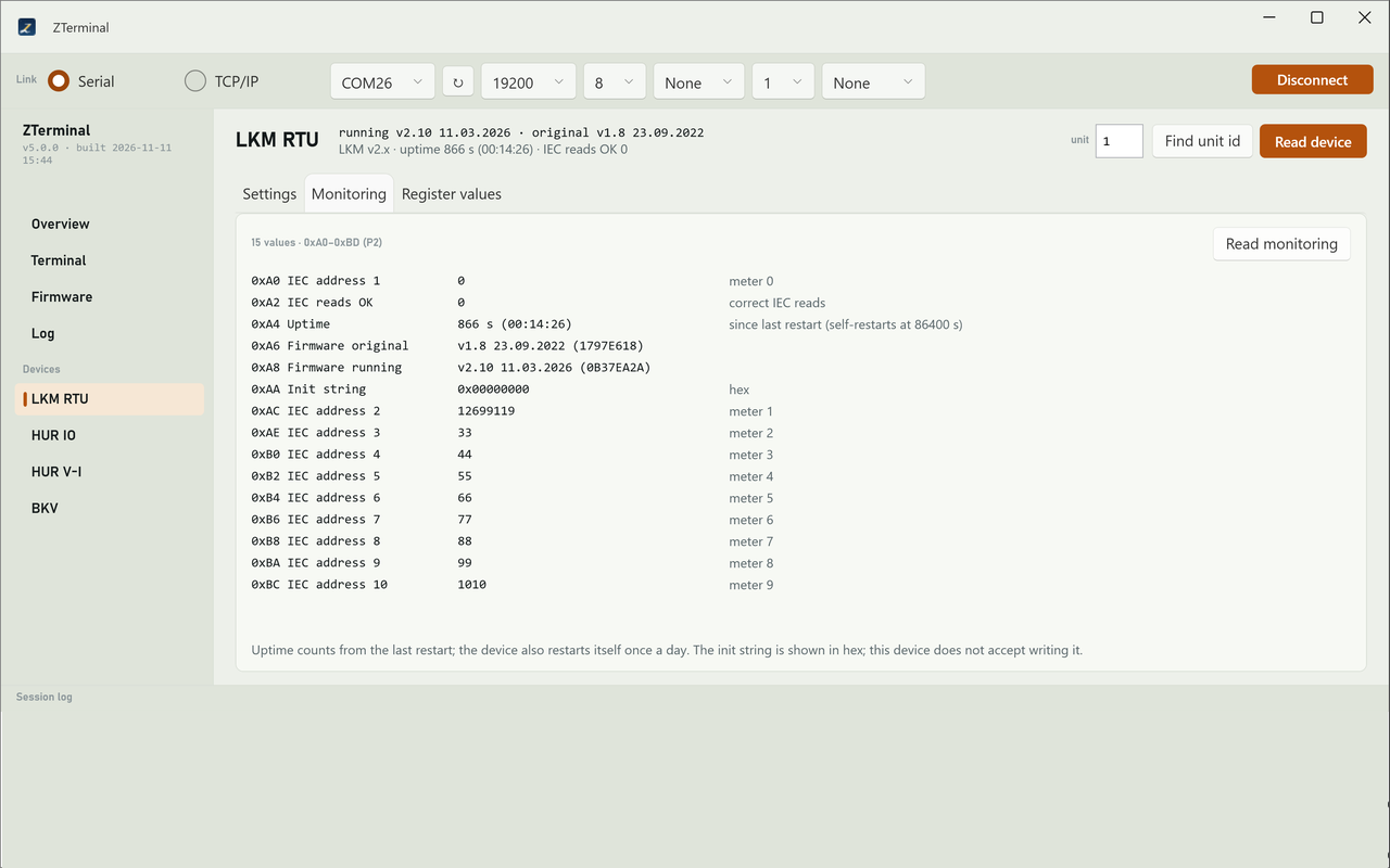
Read device reads the firmware versions, the settings, the IEC addresses and the 15 monitoring values, and fills the Monitoring tab with them.
Next to the title you then see the running and the original firmware version. Under them you see the uptime and how many correct IEC reads the LKM has made.
When you open a tab that has no values yet, ZTerminal reads it once by itself. A tab that already shows values is not read again until you press its button.
If a request fails, a red line under the header says which action failed and why; the log has the same line.
When the connection closes, the page clears the identity, the settings, the IEC addresses and the values on the Monitoring and Register values tabs.
6.2 Settings
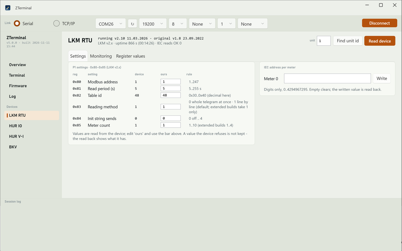
The settings card has one row per setting. setting is its name, device the value read from the LKM, ours the value you want and rule the values the LKM accepts. The card has six settings.
| Setting | Values the LKM accepts |
|---|---|
| Modbus address | 1 to 247 |
| Read period (s) | 5 to 255 |
| Table id | 48 to 64, entered in decimal |
| Reading method | 0 the whole telegram at once, 1 line by line (the default; extended builds accept only 1) |
| Init string sends | 0 (off) to 4 |
| Meter count | 1 to 10 (extended builds 1 to 4) |
As soon as a value in ours differs from the device, a bar appears above the card. It says how many settings will be written and lists each new value. Discard puts every value back to what the device holds. Write and read back writes the changed settings.
Before anything is sent, ZTerminal checks every changed value against the rule. If one value is not a number or is outside the rule, a red line names the setting and the reason, and nothing is written. If the device has not been read yet, the line says "Read the device first."
ZTerminal writes the settings one at a time and the Modbus address last; after a new address is written, the unit box switches to it. If the device does not answer a value, it has not kept it: ZTerminal stops there, says which value was not kept and reads the device again, so the table shows what the device really holds. When all values were taken, a line under the settings says how many were written and read back.
There is no extra confirmation: Write and read back writes at once. To undo a change, enter the old value in ours and write again.
6.3 IEC address of each meter
The IEC address per meter card has one row for each meter the LKM is set to read, numbered from Meter 0. Each row shows the address read from the device. Change it and press the row's Write button: that one address is written at once and the row then shows the address read back from the device. An empty box clears the address.
An address has digits only: it is a 32-bit number, and letters are refused before anything is sent.
6.4 Monitoring
On the Monitoring tab, Read monitoring reads 15 values: IEC address 1, IEC reads OK (correct IEC reads), Uptime, Firmware original, Firmware running, Init string and IEC address 2 to IEC address 10. The firmware values are shown as version and date, the init string in hex, and the uptime in seconds and as days, hours, minutes and seconds.
The note under the list says that the uptime counts from the last restart and that the device also restarts itself once a day.
6.5 Register values
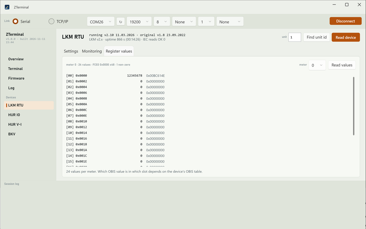
The Register values tab shows the values the LKM has read from one meter. Choose the meter in the meter list and press Read values. The list shows 24 numbered values; next to each value its hex form and, when the highest bit is set, the value read as a signed number. The line above the list says how many values are not zero.
The screen notes: "24 values per meter. Which OBIS value is in which slot depends on the device's OBIS table."
NOTE:
The meter list on the Register values tab offers the meters of the meter count, from 0. It is filled by Read device.
HUR IO
The HUR IO page works with the four HUR IO module types: 8DO (eight digital outputs), 8DI (eight digital inputs), 8AI (eight analog inputs) and 5AO (five analog outputs). The page shows only the parts that belong to the type you select. The HUR V-I module has its own page; see the chapter HUR V-I.
7.1 The header: type and unit id
Choose the module type in the variant list: 8DO - digital output, 8DI - digital input, 8AI - analog input or 5AO - analog output. The device does not report its type, so the choice is yours.
Type the device's Modbus address in the unit box. It starts at 1. Every request on this page goes to that address.
On a serial link the page uses Modbus RTU; over TCP/IP it follows the Device pages choice in the connection strip. The link itself is the one you opened in the connection strip (see the chapter The window).
Read settings reads the device's common settings. The line next to the title then shows the Modbus address, the firmware version (and the newer version if the firmware was updated), the number of reads the device has answered and its uptime. Before the first read the line says "Not read yet."
While a request runs, a thin bar moves under the header. If a request fails, the reason appears in red under the header. Most buttons are disabled while a request runs or while no connection is open; a click on a line's Toggle or Write at that time is ignored or ends with an error.
NOTE:
After every write on this page, ZTerminal reads the values back. Check that the values read back are the ones you wanted. If a write failed, the session log at the bottom of the window gives the reason; see the chapter Log.
NOTE:
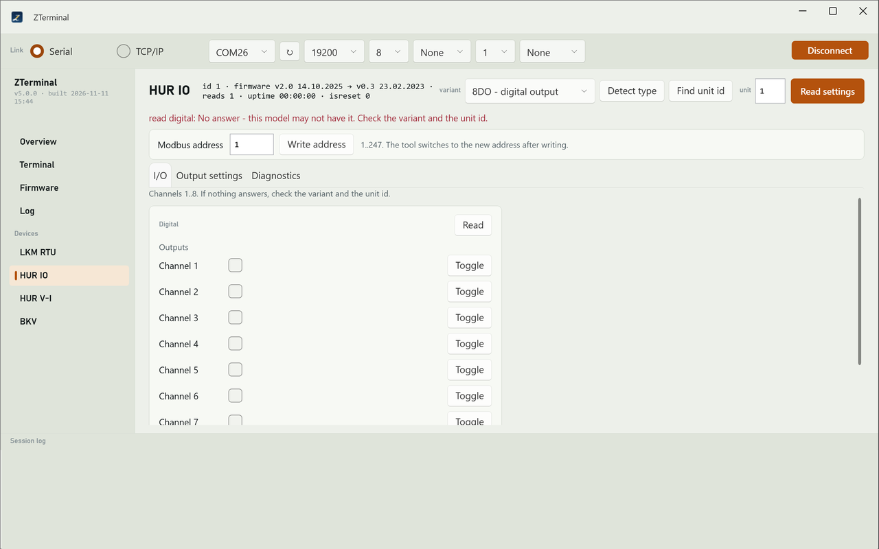
A HUR IO module stays silent when it is asked for something its type does not have. ZTerminal then says that this model may not have it and asks you to check the type and the unit id. A silent device is therefore not always a missing device: check the variant and the unit first.
7.2 Detect type and Find unit id
Detect type asks the device a few read-only questions and selects the type that answered. The result sentence appears on the Diagnostics tab, and the session log lists each question and whether the device answered or stayed silent. Because the device does not report its type, the result is a suggestion: change the variant if you know better.
If nothing answers, the result says "Nothing answered. Check the unit id and the line, or pick the variant by hand."
NOTE:
If the result names V-I, the module is probably a HUR V-I: open the HUR V-I page for it. The variant list on this page then shows no type; choose one again before you use this page.
Find unit id asks the device for its own Modbus address with a broadcast request. When it answers, ZTerminal shows the address next to the title, under the settings line, and puts it in the unit box. If nothing answers, a red message appears and the unit box keeps its value. As the button's tooltip says, only one device may be on the line while you use it.
7.3 Changing the Modbus address
The Modbus address row above the tabs is the same for all four types. Read settings fills the box with the current address.
- Type the new address, 1 to 247. Any other value stops with "Modbus address must be 1..247" and nothing is sent.
- Click Write address. ZTerminal writes the address at once; there is no confirmation window.
- When the device confirms, ZTerminal switches the unit box to the new address and reads the settings again from it. The line next to the title shows the result.
If the write fails, the unit box keeps the old address. To undo a change, write the old address back in the same way while the unit box holds the new one.
7.4 The tabs and automatic reading
The page has three tabs: I/O, Output settings and Diagnostics. Output settings appears only for 8DO and 5AO.
When you open a tab that has not been read yet, ZTerminal reads it once by itself, if a connection is open. This only reads; nothing is written without a click. When you change the variant, the old values are cleared; if I/O is open, it is read again for the new type.
7.5 Digital outputs (8DO)
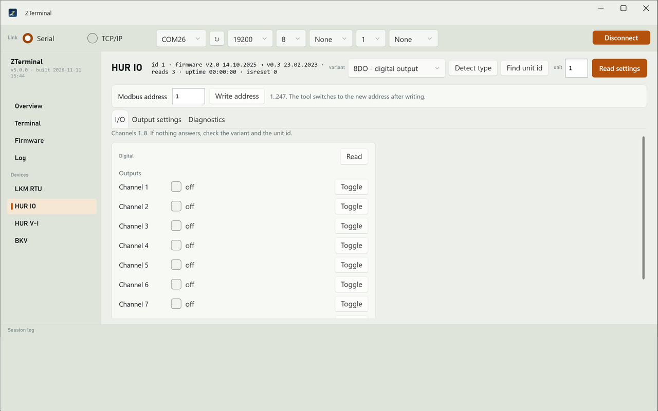
For 8DO the Digital card lists Outputs channel 1 to 8. Read reads the outputs; each line shows ON or off and a tick box set to the same state.
- Toggle switches that output to the opposite of its tick box and reads the outputs back.
- Write all from checkboxes sets all eight outputs as the tick boxes show and reads the outputs back.
Both writes act on the live outputs at once, without a confirmation window. The read that follows shows what the device reports. To undo, set the tick boxes back and click Write all from checkboxes.
7.6 Digital inputs and pulse counters (8DI)
For 8DI the Digital card lists Inputs channel 1 to 8, each ON or off. Read reads them again.
Next to it, the pulse counter card shows one counter per input. The device counts each rising edge of an input. The counters are read only. The card's note says: "Read only. A bouncing contact can add extra counts, and a power cut sets the counters to zero."
Keep counters over the daily restart decides whether the counters survive the device's own daily restart; a power cut still sets them to zero. Read settings sets the box to the device's value. If the device holds a value other than on or off, the box stays undecided and a note shows the value.
- Tick or clear the box. An undecided box stops with "Tick or clear the box before writing."
- Click the Write next to it. ZTerminal writes only this setting and then reads the settings back, so the box shows what the device now holds. To undo, change the box and write again.
7.7 Analog inputs (8AI)
For 8AI the Analog card lists channel 1 to 8. Read reads them. Each line shows the raw reading, 0 to 65535, and next to it the converted value.
Choose 0 - 20 mA or 0 - 10 V in the input type list to match how the input is wired. ZTerminal converts the raw reading in proportion: 65535 is 20 mA or 10 V. As the note next to the list says, the choice only changes how the reading is shown; nothing is written to the device.
After each read a line tells you how many channels answered. A channel that did not answer is shown empty, not with an old value.
7.8 Analog outputs (5AO)
For 5AO the Analog card lists output channel 1 to 5. Read reads the value each output is set to. Each line has a box and a Write button.
- Type the new value, 0 to 1000, in the line's box. After the first read, an empty box holds the current value. A value outside 0 to 1000 stops with a message and nothing is sent.
- Click Write. ZTerminal sets the output at once, without a confirmation window, and reads the outputs back; the line shows the value the device now reports.
To undo, write the earlier value back.
7.9 Output settings (8DO and 5AO)
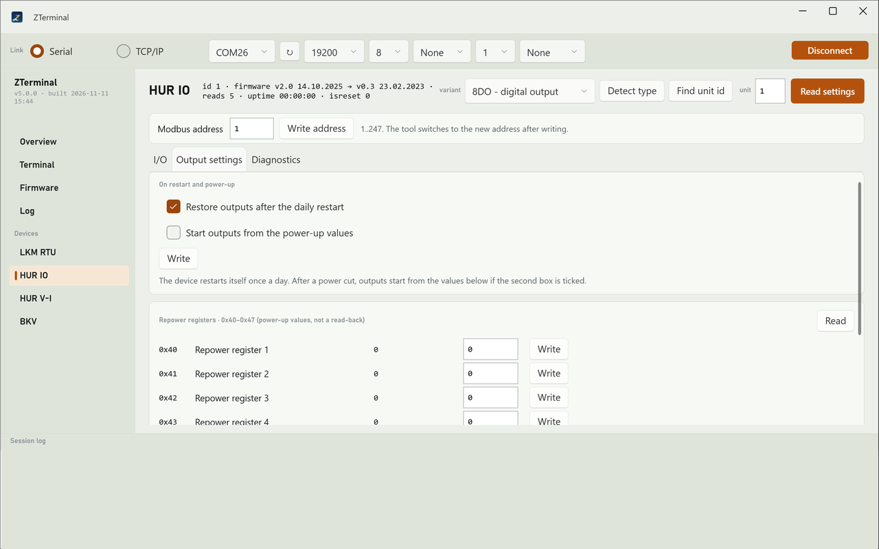
The Output settings tab decides what the outputs do when the device starts. Its On restart and power-up card has two boxes. The card's note says: "The device restarts itself once a day. After a power cut, outputs start from the values below if the second box is ticked."
- Restore outputs after the daily restart: whether the outputs return to their earlier state after the device's daily restart.
- Start outputs from the power-up values: after a power cut, each output starts from its power-up value in the card below.
Read settings sets both boxes from the device. A box stays undecided, with a note showing the value, when the device holds something other than on or off.
- Tick or clear both boxes. If one is undecided, ZTerminal stops with "Tick or clear both boxes before writing."
- Click the Write under the boxes. ZTerminal writes both settings and reads the settings back, so the boxes show what the device now holds. To undo, change the boxes and write again.
The card below lists the power-up values: eight for 8DO, named Repower register 1 to 8, and five for 5AO, named Power-up value 1 to 5. Read reads them.
- 8DO: each value is 1 (the output starts on) or 0 (the output starts off).
- 5AO: each value is the output's start value, 0 to 1000.
- Type the value in the row's box. A value outside 0 to 65535 stops with a message and nothing is sent.
- Click the row's Write. ZTerminal writes the value and reads the power-up values back. As the card's note says, writing here does not move the live output; the value is used after the next power cut, if Start outputs from the power-up values is ticked.
To undo, write the earlier value back; the read before your change shows it.
7.10 Diagnostics
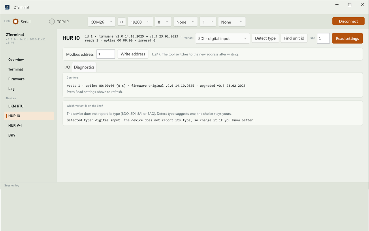
The Counters card on the Diagnostics tab shows the number of reads the device has answered, its uptime (hours:minutes:seconds and seconds), the original firmware version and the updated version, or "not upgraded". The values come from Read settings; press it to refresh.
The Which variant is on the line? card shows the result of the last Detect type.
To update the module's firmware, see the chapter Firmware update.
HUR V-I
The HUR V-I page works with the HUR V-I energy metering module: three voltage and three current inputs. It has six tabs: Metering, Status & config, V-I config, Harmonics, Calibration and Gain & offset.
8.1 The header
Type the module's Modbus address in the unit box; it starts at 1. On a serial link the page uses Modbus RTU; over TCP/IP it follows the Device pages choice in the connection strip (see the chapter The window).
If you do not know the address, tick Find the unit id on the Overview page and click Read there: the read first asks the module for its address. Only one device may be on the line for that. See the chapter Overview.
Read settings reads the module's common settings. The line next to the title then shows the Modbus address, the firmware version, the number of reads the module has answered and its uptime.
While a request runs, a thin bar moves under the header. If a request fails, the reason appears in red under the header. Most buttons are disabled while a request runs or while no connection is open; a click on a row's Write at that time is ignored or ends with an error.
When you open a tab that has not been read yet, ZTerminal reads it once by itself, if a connection is open. On the Gain & offset tab this reads the gains only. This only reads; nothing is written without a click.
WARNING:
The write buttons on this page change the module's metering configuration and calibration. There is no confirmation window: a write starts when you click. Each section below says which conditions ZTerminal checks before it writes, how it reads the result back and how to undo the change. Read a tab before you change it.
NOTE:
After a write, check that the values read back are the ones you wanted; a note saying that something was written does not prove it. If a write failed, the session log at the bottom of the window gives the reason; see the chapter Log.
8.2 Metering
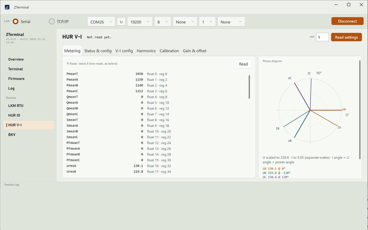
Read on the Metering tab reads the module's 71 measured values in two requests and lists them by name, each with up to three decimals.
| Names | What they are |
|---|---|
| PmeanT, QmeanT, SmeanT, PFmeanT and the A, B, C rows | Active, reactive and apparent power and power factor: total and per phase |
| UrmsA to UrmsC, IrmsA to IrmsC, IrmsN0 | Voltage and current per phase, and the neutral current |
| Frequency, Temperature | Line frequency and the module's temperature |
| PAngleA to PAngleC, UangleA to UangleC | Power angle and voltage angle per phase |
| PmeanTF to PmeanCH | Fundamental and harmonic active power, total and per phase |
| THDNUA to THDNIC | Total harmonic distortion of voltage and current per phase |
| FwdActiveT to ApparentC | Forward and reverse active and reactive energy, and apparent energy: total and per phase |
| UrmsA_LSB to IrmsC_LSB | The low-order part of the voltage and current readings |
The Phase diagram next to the list is drawn from the same read. It shows the three voltages UA, UB, UC and the three currents IA, IB, IC as arrows from the centre, one colour per phase; the current arrows are thinner. A voltage arrow points at the voltage angle; a current arrow points at the voltage angle plus the power angle of its phase. Voltages and currents have separate scales, so a small current stays visible next to a large voltage; the note under the diagram gives both scales. The list under it, and the tooltip of each arrow, give each arrow's size and angle.
Before the first read the note says "Read the metering values to draw the phase diagram."
8.3 Status and configuration registers
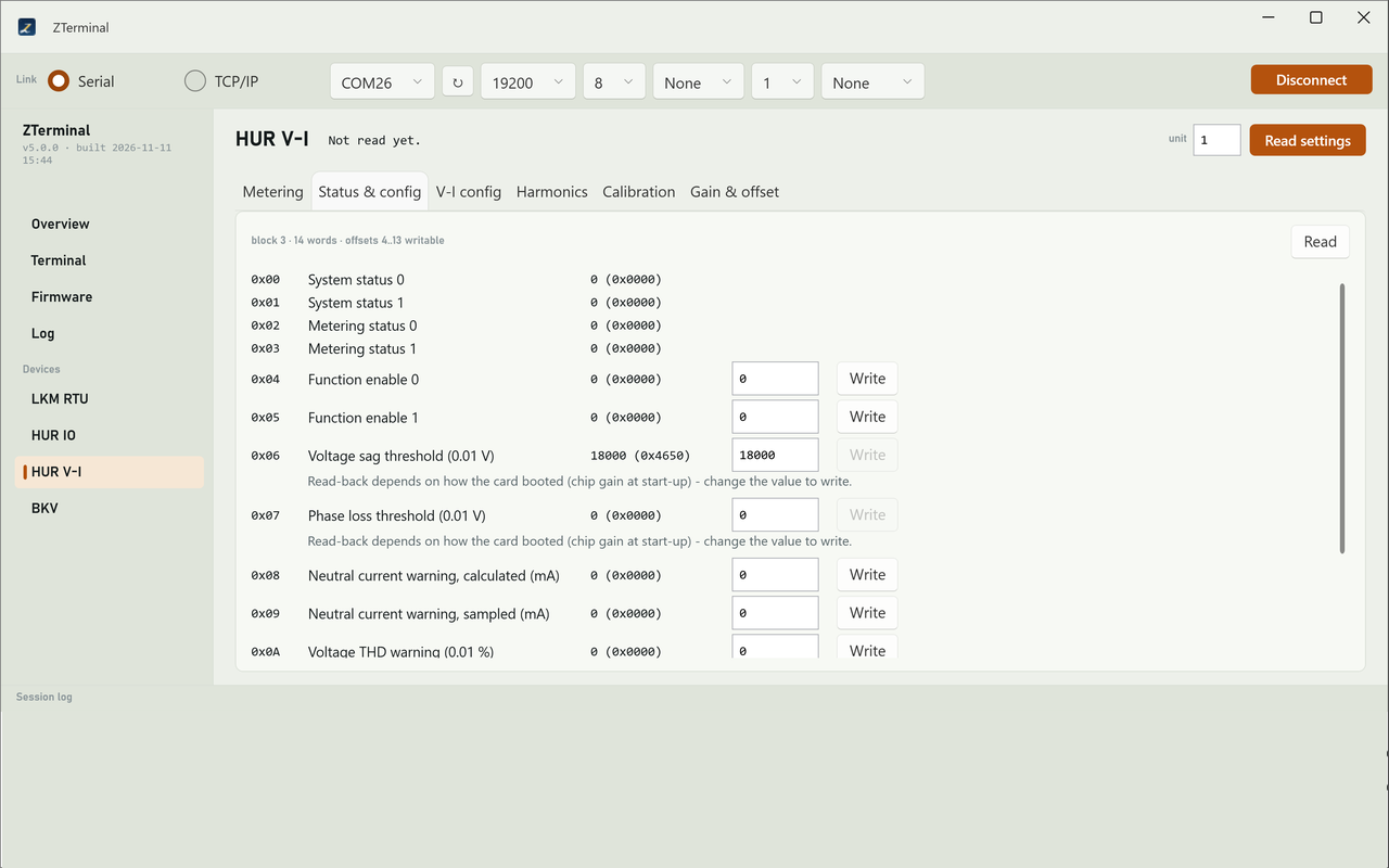
The Status & config tab shows the module's 14 status and configuration registers as numbers. Read reads them; each row shows the value in decimal and hexadecimal. The first four rows, System status 0, System status 1, Metering status 0 and Metering status 1, are read only. The other ten rows have a box and a Write button.
The writable rows are the two function enable registers, the six thresholds (their units are in the row names, for example Voltage sag threshold (0.01 V)) and the two metering mode registers. The V-I config tab shows the same registers field by field.
- Type the new value in the row's box. A value outside 0 to 65535 stops with a message and nothing is sent.
- For Voltage sag threshold (0.01 V) and Phase loss threshold (0.01 V), Write stays disabled while the box holds the value that was read. The note under these rows explains why: "Read-back depends on how the card booted (chip gain at start-up) - change the value to write."
- Click Write. ZTerminal writes that one register and reads the tab again, so the row shows what the module now reports.
To undo, type the value shown before your change and write it again.
8.4 V-I configuration
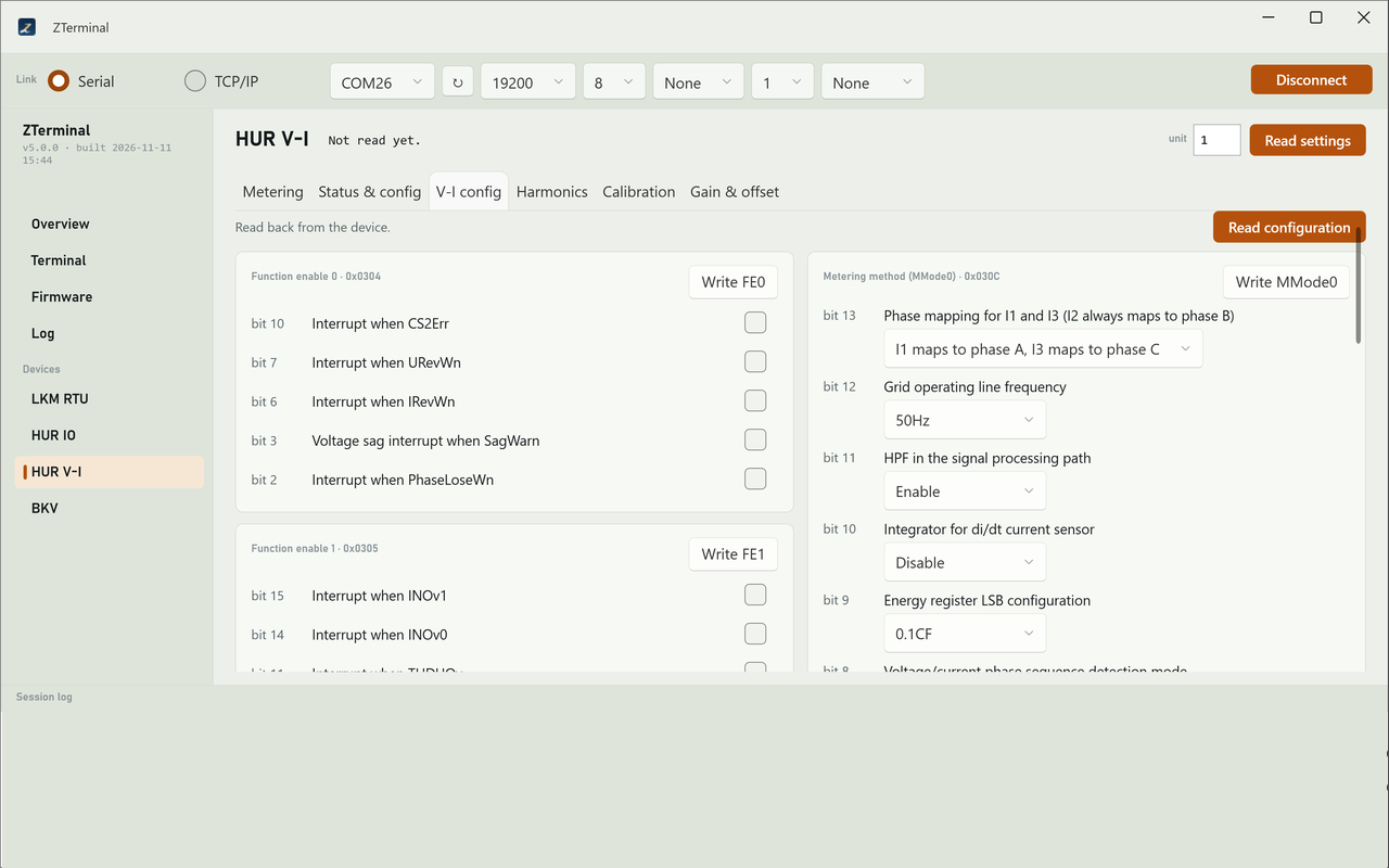
The V-I config tab shows the configuration registers field by field. Read configuration reads them. Each field row shows which bit it uses; an on / off field has a tick box, a field with choices has a list.
| Card | What you set | Button |
|---|---|---|
| Function enable 0 | Which warnings raise an interrupt, for example Voltage sag interrupt when SagWarn | Write FE0 |
| Function enable 1 | More interrupt sources, and the energy direction-change flags per phase | Write FE1 |
| Thresholds | The six threshold values, as numbers, each with its own Write | per row |
| Metering method | For example Grid operating line frequency (50Hz or 60Hz), the phase sequence mode and how the totals are calculated | Write MMode0 |
| PGA gain | The gain of each voltage and current input: 1, 2 or 4 (Digital PGA also 8) | Write MMode1 |
After a read the note at the top says "Read back from the device." If the module has options on in a function enable register that none of the fields shows, the note instead says so and warns that writing the register turns them off.
- Read the tab first with Read configuration, so that every field shows the module's current value.
- Change the fields on one card.
- Click the card's write button. ZTerminal writes the whole register exactly as the card's fields show - a bit that has no field on the card is written as off - and then reads the configuration again; the fields then show what the module reports.
The threshold rows follow the same rules as on the Status & config tab, including the disabled Write for the sag and phase loss thresholds until you change the value. After a threshold write ZTerminal reads the configuration again.
To undo a card's write, set the fields back as they were and write the card again. You can also note the register's number on the Status & config tab before you change anything, and write that number back there.
8.5 Harmonics
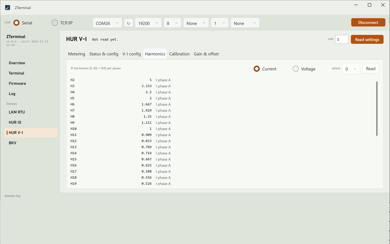
The Harmonics tab shows the 2nd to 32nd harmonic and the total harmonic distortion of one phase. Choose Current or Voltage, choose the phase (0, 1 or 2 for phase A, B or C) and click Read. The rows are named H2 to H32 and THD.
With the harmonics ZTerminal also reads that phase's voltage and current. If the phase has no current (0.01 A or less) for current harmonics, or no voltage (10 V or less) for voltage harmonics, a red note says that the harmonics and the distortion value are meaningless without it.
8.6 Calibration registers
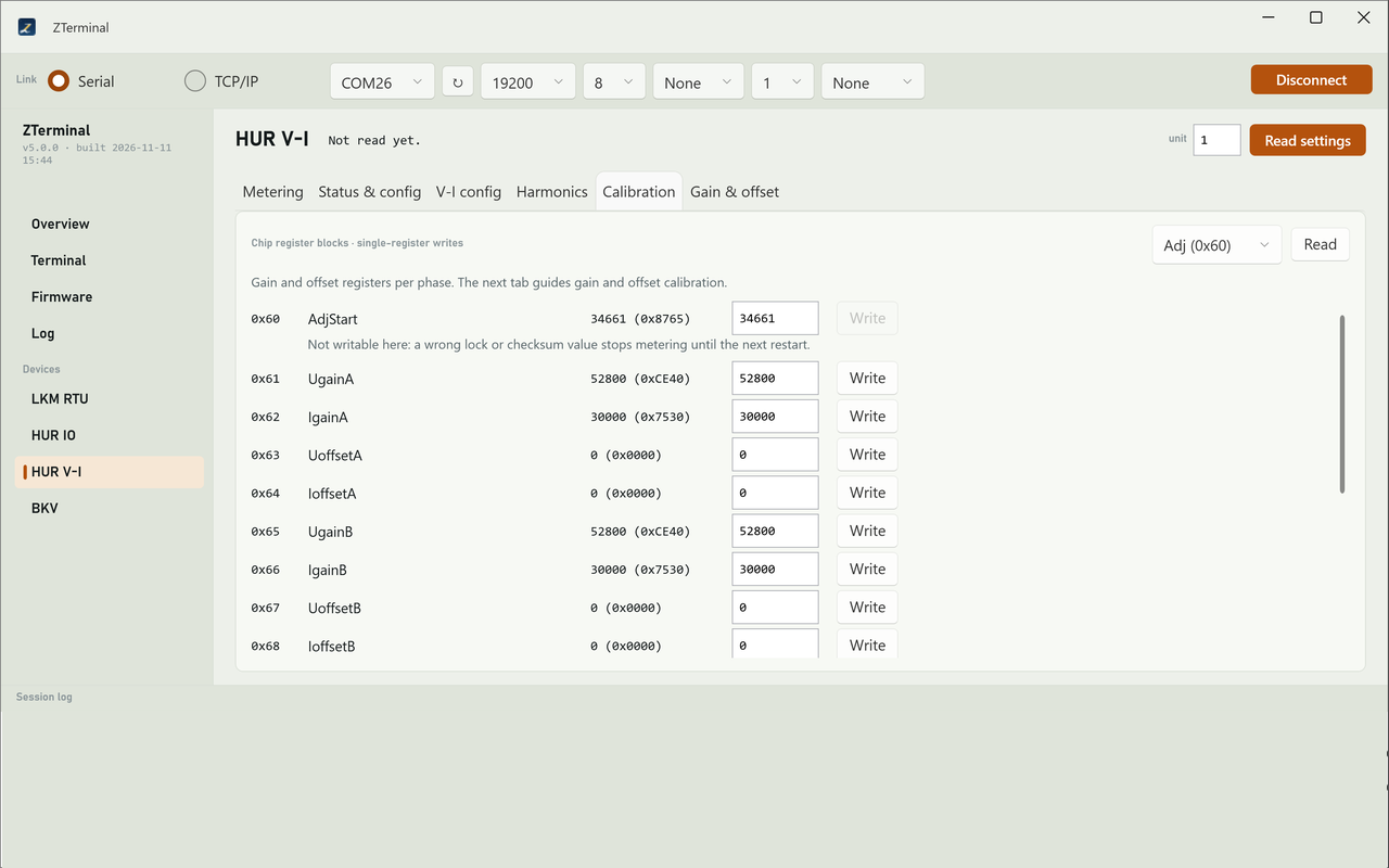
The Calibration tab shows the metering chip's calibration registers one block at a time. Choose the block in the list next to Read - Config, Cal, Harm, Adj (the default) or Raw RMS - and click Read. Each row shows the value in decimal and hexadecimal. The Adj block holds the gain and offset registers per phase; the Gain & offset tab guides their calibration.
Write is enabled only on the 14 gain and offset rows of the Adj block, UgainA to IoffsetN. Raw RMS rows are read only. On every other row Write is disabled and a note gives the reason:
- AdjStart and CS3: "Not writable here: a wrong lock or checksum value stops metering until the next restart."
- Config, Cal and Harm rows: "Not writable here: the device does not keep this block after a restart, and one write may reset the rest of it."
- Type the new value in the row's box, 0 to 65535.
- Click Write. ZTerminal writes that one register and reads the block again, so the row shows what the module now reports.
To undo, type the value shown before your change and write it again. Keep the block selected in the list while you do this: the read after a write reads the block the list shows.
8.7 Gain calibration
The Gain & offset tab guides the calibration of the seven gain registers (UgainA, IgainA, UgainB, IgainB, UgainC, IgainC, IgainN) and the seven offset registers. In the gain card the columns are register, address, on device, default, adjust and will write.
Read gains fills on device with the values the module holds. The first Read gains after ZTerminal starts also fills default; later reads leave default as it is until you change it or close ZTerminal. After a restart of ZTerminal, default holds what the module held at that first read. The note says "Gain registers read. 'Default' is the base the adjustment is added to."
- Type the adjustment for each register in adjust, as a whole number that may be negative. The value written is default plus adjust, limited to 0 to 65535. will write shows that value as computed at the last Read gains.
- Check that every row has a default from 0 to 65535 and a whole-number adjust. Otherwise ZTerminal stops with a message naming the row, and nothing is sent. Before the first Read gains the defaults are empty, so read the gains first.
- Click Write gains. ZTerminal writes all seven gain registers, each as default plus adjust at the moment you click, and then reads the gains again; on device shows the result.
To undo, set every adjust to 0 and click Write gains: ZTerminal writes the default values back, which are the values of the first Read gains since ZTerminal started, unless you changed them. If you may need them after closing ZTerminal, note them before you write.
8.8 Offset calibration
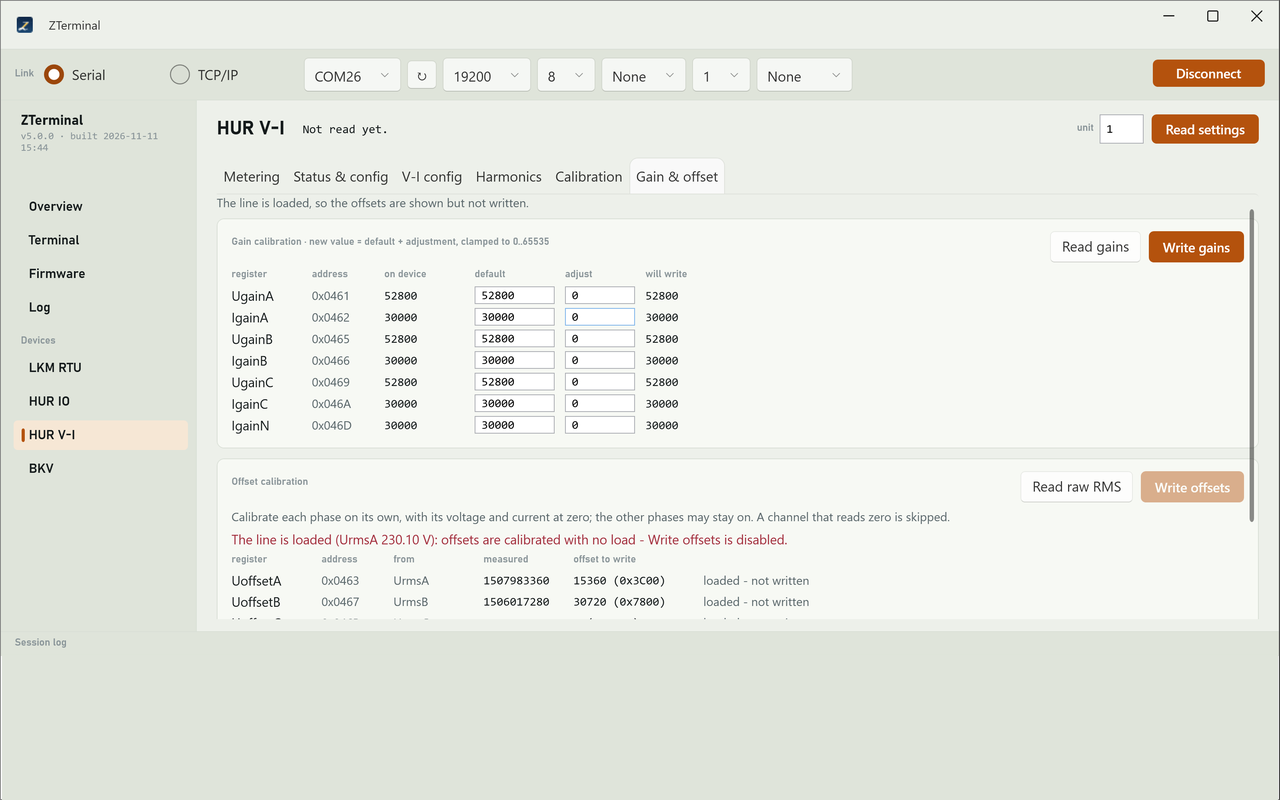
The offset card calculates the seven offset registers (UoffsetA, UoffsetB, UoffsetC, IoffsetA, IoffsetB, IoffsetC, IoffsetN) from the module's raw readings. The columns are register, address, from (the raw reading it comes from), measured, offset to write and a status. The card's note says: "Calibrate each phase on its own, with its voltage and current at zero; the other phases may stay on. A channel that reads zero is skipped."
- Set the phase you calibrate to zero voltage and zero current. The other phases may stay on.
- Click Read raw RMS. ZTerminal reads the raw values ten times and calculates the phase offsets from the average; IoffsetN comes from the last of the ten readings. A channel that reads zero shows - and is skipped.
- Check the status column. will be written marks the rows ZTerminal will write: a phase's two rows only when that phase showed 10 V or less and 0.01 A or less in all ten readings, and IoffsetN only when all three currents were 0.01 A or less. Rows of a phase that carried voltage or current show loaded - not written, and a note names the loaded phases.
- Click Write offsets right after the read. ZTerminal writes only the rows marked will be written, with the values calculated at the last Read raw RMS.
If no phase is unloaded, Write offsets is disabled. A red note in the card names a phase that carries voltage (or, if none does, current) and its value, and the note at the top of the tab says "The line is loaded, so the offsets are shown but not written." Read again after you have switched the phase off; the button opens when at least one phase is unloaded.
Clicking Write offsets before any read stops with "Nothing to write - read the raw RMS values first."
NOTE:
ZTerminal does not read the offsets back by itself after Write offsets. To see what the module now holds, read the Adj block on the Calibration tab.
To be able to undo an offset calibration, read the Adj block on the Calibration tab before you start and note the offset values. To return to them, write each value back in its row there.
BKV
The BKV page works with the BKV wM-Bus module. It has four tabs: Device list, Packets, Module and Radio config. The page needs an open connection to the module; see the chapter The window.
9.1 Reading the module
Read BKV wM-Bus reads the module information, its firmware, its clock, the radio configuration and the device list in one round. The line next to the title then shows the module type, the device number and how many devices the module's list holds. If the read fails, the count on that line is not valid; the red line under the title gives the reason.
When you open the page or one of the tabs Device list, Module or Radio config and no read has filled the device number yet, ZTerminal runs this read by itself. It only reads; nothing is written to the module. Like a read you start, it replaces the list on the Device list tab with the module's list.
While a request runs, a thin bar moves under the title and the module buttons wait. If the module does not answer, the red line under the title names the action, followed by "no answer from the module - check the port and that a BKV module is connected."
Restart module asks the module to restart.
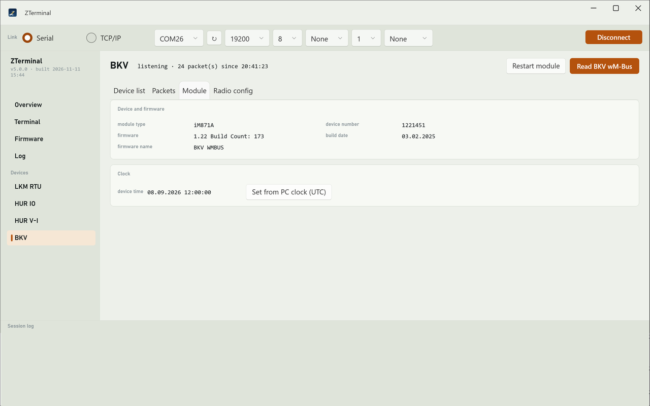
9.2 Module information and the clock
The Module tab shows, under Device and firmware, the module type, the device number, the firmware version, its build date and the firmware name that the module reported.
The Clock card shows the module's device time as it was read.
Set from PC clock (UTC) writes the PC's time, in UTC, to the module. ZTerminal then reads the module's clock back and shows the value it read. If the module refuses the time, or the clock it reports is more than 30 seconds away from the PC's time, ZTerminal says in red that the clock was not set.
9.3 Radio configuration
The Radio config tab holds the module's radio settings: the link mode (receiver off, S-mode, T-mode or C/T-mode), Address filter, the LED flash time (ms), the Notifications over the serial link for received and sent packets, and the LED signals.
The line under the card title shows what the module reported at the last read: its link mode and LED flash time. It is not updated when you change the boxes.
Set radio config writes all boxes of the tab to the module and then restarts the module, as the note next to the button says. Before anything is sent, ZTerminal checks that the LED flash time is between 5 and 5000 ms; otherwise it says so in red and sends nothing.
NOTE:
After Set radio config ZTerminal neither checks the module's answer nor reads the settings back. To see what the module now uses, click Read BKV wM-Bus and check the line under the card title. To go back, set the earlier values in the boxes and write them again.
9.4 The device list
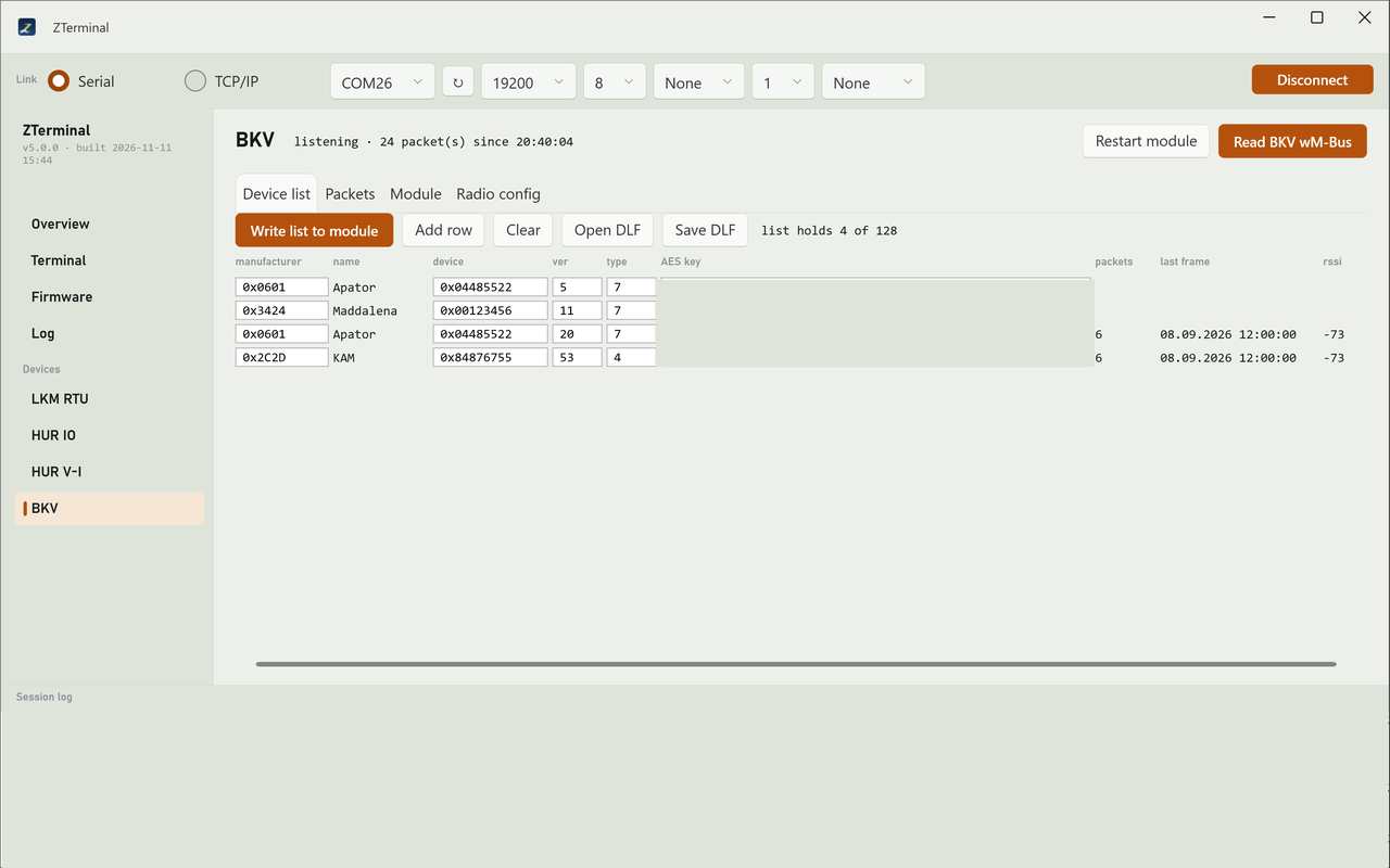
The Device list tab shows the meters the module knows, one row per meter. The columns manufacturer, device, ver, type and AES key are what the module stores, and you can edit them. name shows the manufacturer's name, or its three-letter code, for the number in the first column. packets, last frame (the time of the last packet) and rssi are filled by ZTerminal from the packets it receives; the module does not store them.
Type the manufacturer, the device number and the AES key in hex; spaces, dashes and a leading 0x are allowed. Type the version and the type as decimal numbers.
The line next to the buttons shows how many rows the list held at the last read, file or packet, out of the 128 the module can take.
Add row adds an empty row at the end. Clear empties the list on the screen only; the status says "Device list cleared on this screen (nothing was sent)."
Rows with neither a manufacturer nor a device number are left out when the list is written or saved. Two rows with the same manufacturer, device number, version and type count as one meter.
9.5 Writing the list to the module
Write list to module replaces the whole list in the module with the rows on the screen. ZTerminal first clears the module's list, then sends the rows, asks the module to save the list and restarts the module. When it is done, the status says how many devices were written and, when the module reports it, how many places are still free. An empty list is not written at all.
Before anything is sent, ZTerminal checks the manufacturer, device and AES key of every row. If one of them is not hex, the red line names the row number and the column and says that nothing was written; nothing is sent to the module. Correct that box and write again.
ZTerminal checks the module's answer when it clears, sends and saves the list. If the module refuses one of these steps, the write stops there and the red line says which step failed; when the module took fewer rows than were sent (for example because its list is full), it also says how many rows were written. By then the module's list has already been cleared: remove the cause and write the list again.
WARNING:
The module does not return the AES keys when its list is read, so the AES key column of a list read from the module is empty. Because Write list to module replaces the whole list, a row without a key removes the key the module held for that meter. When rows have no key, the first click on Write list to module writes nothing: the red line says how many devices have no AES key and asks you to press the button again to write anyway. A second click with the same list writes it; if you change a written field (manufacturer, device, version, type or key) or add a row in between, ZTerminal warns again. Keep your device list, with the keys, in a DLF file, and open that file as the last step before the write: Read BKV wM-Bus replaces the list on the screen with the module's list, without keys.
To see the list the module holds after a write, click Read BKV wM-Bus.
9.6 DLF files
Open DLF reads a device list file (CSV, or an Excel file in .xls, .xlsx or .xlsm format) and replaces the list on the screen with it. Nothing is sent to the module. If some lines cannot be read, ZTerminal reads the others, writes each unreadable line to the session log with its line number and the reason, and says "Some lines could not be read - see the log."
Save DLF writes the list on the screen to a file. It suggests an Excel file named ZTerminal_DeviceList.xlsx; give the name the ending .csv to write a CSV file instead. The file holds the meter columns with the AES keys and the packet information (last frame, packet count, date and RSSI), so keep it as carefully as you keep the keys.
Before the file dialog opens, ZTerminal makes the same hex check as for a write; if a box is not hex, the red line names the row and the column and says that nothing was saved.
9.7 Received packets
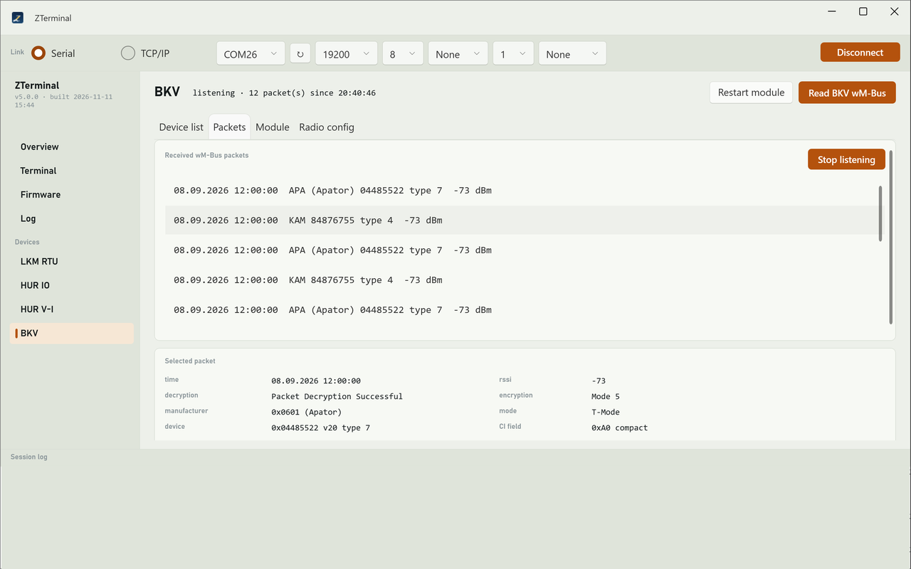
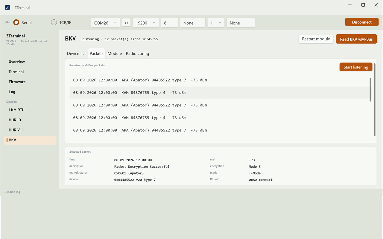
While the BKV page is open and the connection is open, ZTerminal listens for the packets the module receives from meters. On the Packets tab, Stop listening pauses this and Start listening resumes it. Listening stops when you go to another page and starts again when you come back.
Each packet is a row in Received wM-Bus packets: the time, the manufacturer, the device number, the device type and the signal strength in dBm. The newest packet is at the bottom, and the list keeps the last 500. While the last row is selected, the selection moves to each new packet. The line next to the page title counts the packets since listening started.
Each packet also updates the device list: a meter that is not in the list is added as a new row, and for a known meter the packets, last frame and rssi columns are updated. Meters added from packets have no AES key; they are written to the module with the rest of the list and count in the warning about rows without a key. To leave one out, empty its manufacturer and device boxes.
WARNING:
Before you edit the device list by hand, click Stop listening on the Packets tab. Each packet that arrives redraws the list from what was last read or opened, and changes you typed into the rows, or rows you added, are lost. Stay on the BKV page until the list is written or saved: listening starts again when you come back to the page. After the write, click Read BKV wM-Bus to see the module's list.
9.8 The selected packet and its records
Select a packet to see it under Selected packet: the time, the rssi, the manufacturer, the device number with version and type, the radio mode, the encryption mode and the decryption result the module reported, for example "Packet Decryption Successful" or "Packet not Decrypted, No Key Found for WM-Bus Address".
Records lists the data in the packet, one record per row, with its type, value, function and storage number. If the module could not decrypt the packet, the card says "Not decrypted - only the header can be read." When the decryption result says that no key was found or that the key might be wrong, put the meter's correct AES key in the device list and write the list to the module. When it says that the decryption mode is not supported, a key does not help.
Raw frame shows the packet as received, in hex, for support.
Firmware update
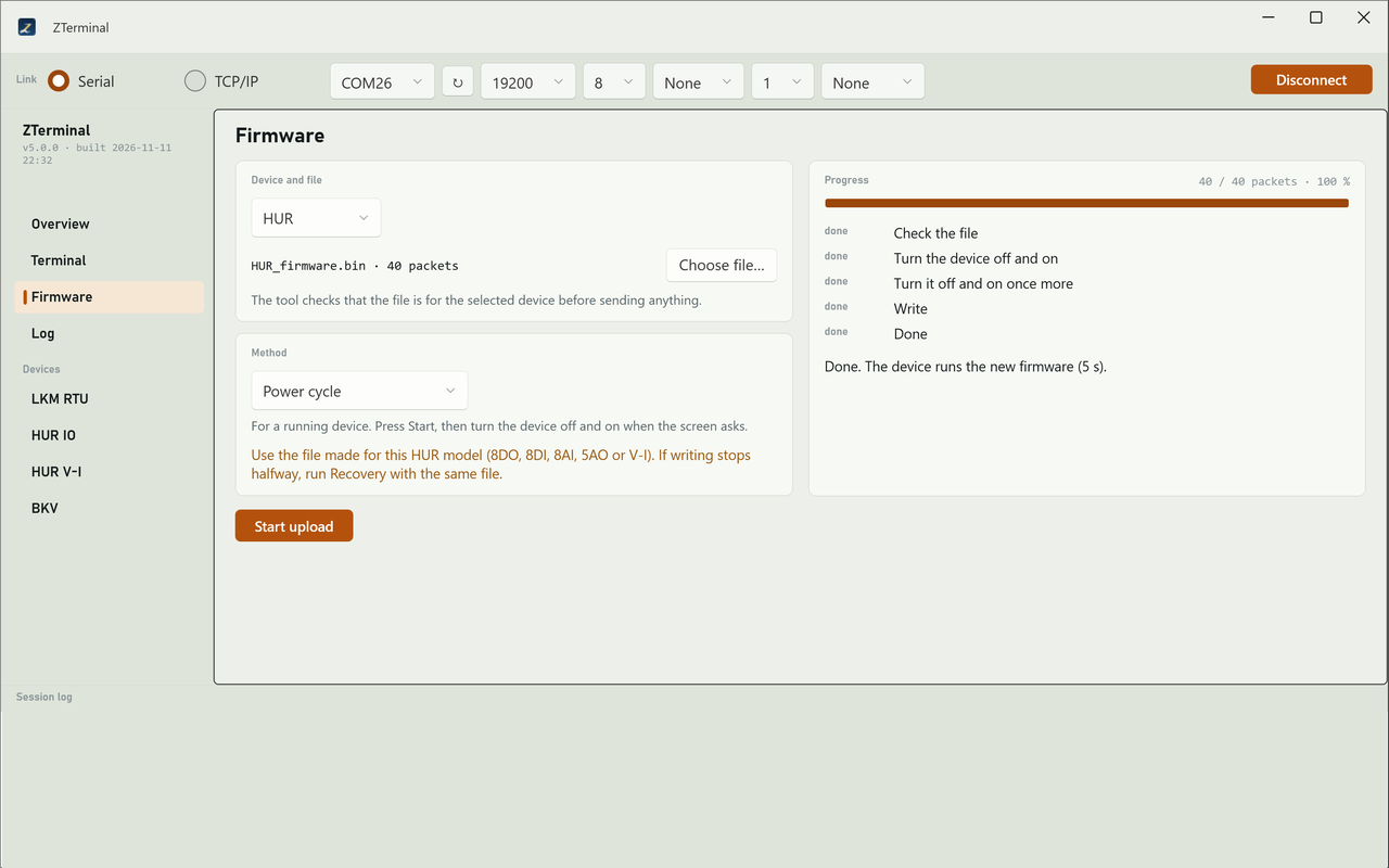
The Firmware page loads a new firmware file into an LKM or a HUR device over the connection you opened in the connection strip. You choose the device and the file, choose the method, and start. The page then tells you, step by step, when to turn the device off and on.
10.1 Choosing the device and the file
In the Device and file card, choose LKM or HUR in the list, then click Choose file... and pick the firmware file (a .bin file). The line next to the button shows the file name and the number of packets it will be sent in; when the file name carries a version and a date, the line shows them too. Choosing a file sends nothing to the device.
As the card says, ZTerminal checks that the file is for the selected device before sending anything. It checks that the file is complete (its length matches the length written inside it) and that the hardware type written inside it is the one of the device you chose. If the file fails, a red sentence under the file line says that the file is for the other device, or that it is not a firmware file for the selected device. The check runs again when you change the device in the list.
Start upload works only while a connection is open and a file that passed the check is chosen. ZTerminal checks the file once more when the update starts; if it is refused then, the result says "This file is not for the selected device. Nothing was sent."
WARNING:
For a HUR device the card under Method says "Use the file made for this HUR model (8DO, 8DI, 8AI, 5AO or V-I). If writing stops halfway, run Recovery with the same file." ZTerminal's check tells an LKM file from a HUR file, but all HUR models carry the same hardware type, so the check cannot tell which HUR model a file was made for. Choosing the file for the right model is up to you.
10.2 The two methods
Choose the method in the Method card. The note under the list says what each one is for:
- Power cycle: "For a running device. Press Start, then turn the device off and on when the screen asks." ZTerminal asks you to turn the device off and on twice.
- Recovery: "For a device stuck in update mode. Press Start, then turn the device off and on once." Use it after an update that stopped while writing.
For an LKM device the card also says "If writing stops halfway, run Recovery with the same file."
10.3 The connection during an update
Connect with the settings you use for the device's normal work. On a serial connection ZTerminal sets the port itself for the device's loader: for an LKM it keeps the speed you connected with and sets 8 data bits, no parity, 1 stop bit; for a HUR it switches the port to 19200 baud, 8 data bits, no parity, 1 stop bit.
Through a TCP gateway ZTerminal cannot change the speed. If a HUR update through a gateway stops, the result adds that the HUR loader talks at 19200 baud, 8N1: set the gateway (or adapter) to that and start again.
NOTE:
After an update, click Disconnect and then Connect before you use the device pages. ZTerminal may change the port's speed and framing for the loader, and an update that stops leaves them changed.
Leave the connection open and stay on the Firmware page until the result appears. Other pages read the same line: the Terminal and BKV pages start reading it as soon as you open them.
10.4 Running the update
Click Start upload. The Progress card lists the steps of the method, and each step shows its state: now while it runs, done when it is finished, failed if the update stopped there.
- Power cycle: Check the file, Turn the device off and on, Turn it off and on once more, Write, Done.
- Recovery: Check the file, Turn the device off and on, Write, Done.
When ZTerminal needs you, the step shows what to do and a countdown of the seconds left. Do it while the countdown runs:
- Turn the device off and on: the step says "Turn the device off, wait a few seconds, turn it on." With Power cycle you have up to 20 seconds; ZTerminal calls the device during that time and goes on as soon as the device answers, and the device listens only in the first seconds after it is turned on. With Recovery this is the only power step and it has 30 seconds.
- Turn it off and on once more (Power cycle only): the step says "Turn the device off and on once more." It has 30 seconds. ZTerminal sends nothing and waits for the device to report that it is ready for the file.
- Write: the file is sent packet by packet. The bar and the counter above it show the packets sent, out of the total, and the percentage.
While the update runs, a box says "Updating. Do not turn the device off unless a step asks you to."
NOTE:
With a HUR device the power step can come back: if the device's loader locks up on the first packet and refuses everything after it, ZTerminal shows the step again and asks you to turn the device off and on once more, at most two more times. If the loader is still locked, the update stops.
When every packet is accepted, all steps show done and the result says that the device runs the new firmware, with the time the update took. To see the version the device now reports, read it again on its page or on the Overview page.
10.5 When an update stops
Once started, an update runs to its end. ZTerminal stops it by itself when the device does not enter update mode, or does not accept a packet after six tries, and marks the step where it stopped as failed. The result line then says what state the device is in and what to do. The session log has the details (see the chapter Log).
"The device did not enter update mode and keeps its firmware. Start again and turn it off and on when the screen asks." Nothing was written. If you did not turn the device off and on at the second step and the device does not work afterwards, it is waiting in update mode: use Recovery with the same file.
"The device did not accept the file and stays in update mode. Run Recovery with the same file." The device has left its firmware and waits for a file.
If writing stops halfway, the result says at how many packets it stopped and that the device stays in update mode. The device then has no working firmware until a file is loaded.
- Keep the connection open. Turning the device off and on alone does not bring the old firmware back.
- On the Firmware page choose the same device and the same file.
- Choose Recovery and click Start upload.
- When the step Turn the device off and on asks, turn the device off and on once.
If Recovery stops too, the result says the device stays in update mode and asks you to run Recovery again, for example "The device did not take the file and stays in update mode. Check the file and the device, then run Recovery again."
If the page shows "The update stopped unexpectedly. See the log.", save the session log and contact support (see the chapter Troubleshooting).
Log
The Log page shows the session log: everything ZTerminal records while it runs, one line per event, the newest at the bottom. It is the same log as the Session log panel at the bottom of the window, with more room, a filter, a find box and saving.
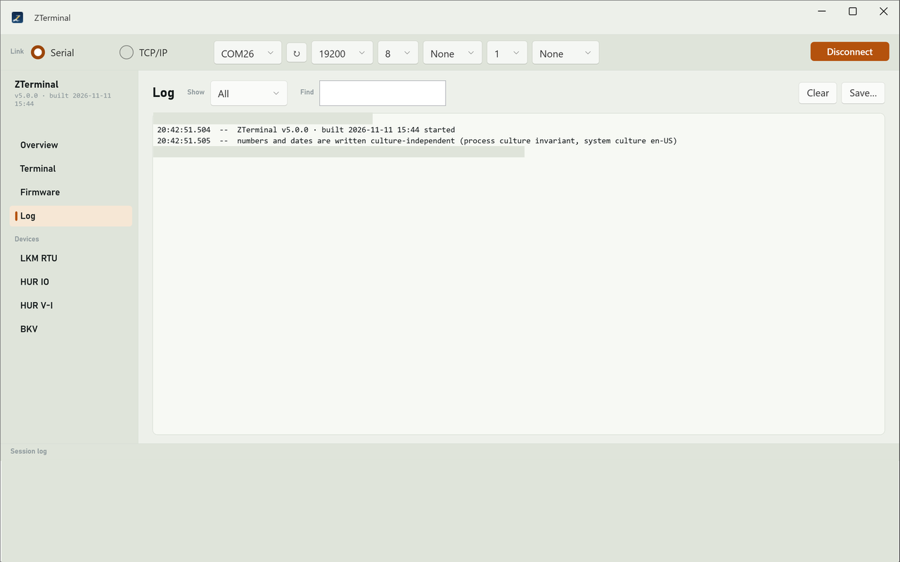
Each line starts with the time, to the millisecond, and a tag:
- TX - bytes ZTerminal sent, in hex;
- RX - bytes ZTerminal received, in hex;
- !! - a warning;
- XX - an error;
- -- - information.
The log starts with the place of the settings file and the version of ZTerminal. After that it records the connections you open and close and why a connection could not be opened or was lost, the data that the terminal and the device pages send and receive, line errors of a serial port, and the warnings and errors of every page.
11.1 Filtering and finding
Show narrows the list: All shows every line, TX only the sent bytes, RX only the received bytes and Warnings the warnings and errors. The filter applies to this page only - the Session log panel always shows all lines - and ZTerminal remembers it after a restart.
Find jumps to the lines that contain your text among the lines the filter shows; case does not matter and no line is hidden. Press Enter for the next match and Shift+Enter for the previous one; the counter next to the box shows where you are.
The page shows the newest 2000 lines. Select lines with Shift or Ctrl (Ctrl+A selects all) and press Ctrl+C, or right-click for Copy and Copy all, to paste them into a message.
11.2 Clearing the view
Clear empties the list on this page and the Session log panel, so that you see only what happens next. It does not delete the session log itself: the line next to the find box says how many lines the session log still keeps, and saving still writes all of them.
11.3 Saving the log for support
Press the Save button at the top right of the page and choose where to save. The file name proposed contains the date and time. ZTerminal writes the whole session log to a text file, whatever the filter shows and also after Clear; the line next to the find box says how many lines were saved. The session log holds the newest 20000 lines; older lines are dropped.
The session log is kept only while ZTerminal runs; it is not written to disk by itself. When something goes wrong, save the log before you close the program and send the file to support, together with a short description of what you did. Near the start of the file a line gives the version, unless the log has grown past 20000 lines.
NOTE:
The Save log as text button on the Terminal page writes the same file content.
NOTE:
If the window of ZTerminal meets an error it cannot recover from, a message says so, names the file the details were written to, and the program closes. An error in work that runs in the background can close the program without a message; its details go to the same file, in the same folder as the settings file. Send that file to support as well.
Troubleshooting
This chapter lists what ZTerminal shows when a connection does not open or a device does not answer, and what to send to support. Each page also shows its own problems in red under its title.
12.1 A connection that does not open
The text next to the Connect button says what happened. A line about it is also written to the Session log at the bottom of the window.
"Choose a COM port (none found - refresh after plugging the adapter)": Windows reports no serial port. Plug in the adapter and click the Refresh COM ports button next to the port list. After a refresh ZTerminal keeps the port you had chosen; if it is gone, it selects the last port in the list, so check the choice.
If the port does not open, the text says that ZTerminal could not open the port, with the reason Windows gave, for example when another program is using the port. With an uncommon framing (5 or 6 data bits, mark or space parity, or 1.5 stop bits) the text adds that the adapter's driver may not support it; choose another framing or another adapter.
For TCP/IP, ZTerminal first checks the boxes: "Enter a host or IP address" when the host box is empty, a note that the TCP port must be between 1 and 65535, and "Sockets must be 1..32" for the number of sockets.
If the other end does not accept the connection within 5 seconds, the text says that there was no answer from that host and port. Check the address, the port and that the device or gateway is on the network. With Force Reconnect ticked, ZTerminal keeps trying every 2 seconds until the connection opens or you click Cancel.
While ZTerminal is connecting, the button reads Cancel; clicking it stops the attempt and the text says "Connection cancelled".
While the Terminal page is open, ZTerminal notices a broken connection, closes it, and the text starts with "Link lost", followed by the connection's name and the reason. On TCP, Force Reconnect then connects again by itself. A TCP endpoint that disappears without closing the connection is noticed only when something is sent, unless TCP keepalive is ticked; then ZTerminal notices it in about 20 seconds. On a device page a broken connection shows as a device that does not answer: click Disconnect and Connect again.
12.2 A device that does not answer
The device pages work only while a connection is open; without one their entries in the left bar are not available. ZTerminal talks to the device with the speed and framing chosen in the connection strip, so these must match the device's settings. After a firmware update, click Disconnect and Connect first (see the chapter Firmware update).
Then check, in this order:
- The unit id. It must be the device's Modbus address. With only one device on the line, Find unit id on the device page asks the device for its own id; on the Overview page, tick Find the unit id and click Read.
- Over TCP/IP, the Device pages choice in the connection strip: Modbus TCP for a device or gateway that talks Modbus TCP, RTU over TCP for a serial server that passes the bytes on unchanged. On a serial link there is nothing to choose: the device pages always use Modbus RTU.
- The product. On the Overview page, choose the product that is really on the line.
The Overview page names the cause it suspects: "no reply - check the unit id, the framing and which product is actually on the line", "no reply within the timeout - check the link and which product is on it", or, when it was asked to find the unit id, "no device told its unit id - check the link and that only one device is on the line".
On the HUR IO page, a HUR module stays silent when it is asked for something its type does not have. ZTerminal then says that this model may not have it; it says the same when nothing answers at all, for example at a wrong unit id. Check the variant and the unit id (see the chapter HUR IO).
A BKV module has no unit id. If it does not answer, the BKV page says "no answer from the module - check the port and that a BKV module is connected."
An LKM device can miss the first request after traffic at another speed on the same line. ZTerminal sends the first request of each LKM job once more when it gets no answer, and notes this in the session log.
A device whose firmware update stopped while writing waits in update mode and does not answer on its page. Load the firmware again with the Recovery method (see the chapter Firmware update).
12.3 When ZTerminal closes with an error
If ZTerminal hits an error it cannot recover from, a message says so, shows the error and the place where the details were written, and ZTerminal closes. The details go to a file named crash.log in a ZTerminal folder of your user profile's local application data; the message shows its full location. Send that file to support.
An error in work that runs in the background is written to the same file without a message, and ZTerminal may close without one. If ZTerminal disappears, look for that file.
12.4 What to send to support
Save the session log right after the problem. On the Log page, click Save... and choose where to write the file; ZTerminal suggests a name that starts with zterminal-log and carries the date and time. The file holds the whole session log, also the lines you cleared from the view, up to the newest 20000 lines. The Terminal page's Save log as text... writes the same log. ZTerminal keeps the log only while it runs, so save it before you close ZTerminal (see the chapter Log).
NOTE:
The session log holds the bytes ZTerminal sent and received. After a device list was written to a BKV module, the log holds the AES keys of that list too.
With the log, send:
- the version shown at the top of the left bar, with its build time;
- the device, its unit id and the firmware version it reports (the Overview page reads it);
- the connection you used: serial with its speed and framing, or TCP/IP with the Device pages choice;
- what you did, in order, and what you expected to see;
- the crash.log file, if ZTerminal closed with an error.
Appendix A: supported devices
ZTerminal for Windows 5.0.0 works with the REDZ devices in the table below. For each one, the table says how ZTerminal recognises it and on which pages you work with it.
| Device | How ZTerminal recognises it | Pages |
|---|---|---|
| LKM RTU | Chosen by you: use the LKM RTU page or choose LKM RTU on the Overview. Shown as LKM RTU v2.x. | Overview; LKM RTU (Settings, Monitoring, Register values); Firmware (LKM) |
| HUR IO: 8DO, 8DI, 8AI and 5AO | The module does not report its type. Detect type on the HUR IO page suggests one; you choose. | Overview; HUR IO; Firmware (HUR) |
| HUR V-I (3 voltage, 3 current) | Chosen by you: use the HUR V-I page or choose HUR V-I on the Overview. | Overview; HUR V-I; Firmware (HUR) |
| BKV wM-Bus collector | Reads the module information. The radio module types iM871A, iM170A and iM881A-XL are named; any other type is shown as UNKNOWN. | Overview; BKV |
The Terminal page is not tied to a device: it sends and receives data on any serial port or TCP connection. See the chapter Terminal.
A.1 Firmware files
The Firmware page updates LKM RTU and HUR modules. Before it sends anything it checks that the file is made for the device you chose there; a file for the other device, or a file that is not a firmware file, is refused. For HUR the page adds: "Use the file made for this HUR model (8DO, 8DI, 8AI, 5AO or V-I). If writing stops halfway, run Recovery with the same file." See the chapter Firmware update.
Appendix B: version history
This manual describes ZTerminal for Windows 5.0.0. The version and the time the program file was built are shown at the top of the left bar.
| Version | Contents |
|---|---|
| 5.0.0 | Pages Terminal, Overview, LKM RTU, HUR IO, HUR V-I, BKV, Firmware and Log. Terminal for serial and TCP connections; identity and diagnostics on the Overview; settings, monitoring and register values for LKM RTU; inputs, outputs and settings for the four HUR IO modules; metering, configuration and calibration for HUR V-I; device list, radio configuration and received packets for BKV; firmware update for LKM RTU and HUR with two methods. |